ARCH501 – Architectural Design Studio II - led by Jim Nicholls
Summary
Taken in the winter of 2009, the Architectural Design Studio II was focused on the structural aspects of design, as well as detailed elements arising from the companion class taught concurrently, ARCH570 Design Development. The studio focused on tectonic aspects of architectural design, with emphasis on development of professional skills in design synthesis, specifically, the unique qualities of materials, construction technology, and assembly details in the expression of architectural ideas. Analysis included the influence of regulatory measures on building form.
Program
The program of this project surrounded the expansion of an existing small, local furniture shop, into a 50,000 sq ft facility in anticipation of commercial growth. The expansion was also to include a private residence for the owner/operator of the business. Focusing on the enhancement of the individual experience of the owner and the artisans who would come to work for him/her, the studio provided an avenue for initial design at a smaller scale (the residence) before the larger industrial facility (the shop expansion) was developed.
Early Exercise.
- A1. Concept Poster: The studio began with an exercise of actual furniture construction; focusing on the creation of a simple stool or table which could both express itself tectonically, and be a theoretically economic viable candidate for the factory we to design. Students had to first develop a design and program for their piece, and then construct it from four inexpensive 2x4s.
- A2. Stool/Table: My design envisioned a robust piece which could serve as either a stool or end table, could easily be made from the inexpensive materials, and could be folded flat for easy packaging, storage and shipment. The design was also flexible enough to allow for changes when unforeseen problems arose construction of the piece itself.
- A2. Stool/Table: Drawings were executed in Sketchup and final construction from four 2x4s.
|
* |
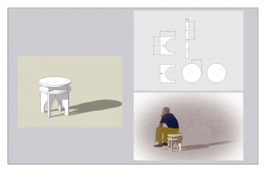 A1. Concept Poster: Shows basic outline of design, break down and intended use of the stool/table. 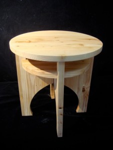 A2. Stool/Table: The final product after construction. Shows modification made to lower level and alternation of fastening method (wood dowels). |
Overview – Plan Views
- B1. Aerial View: The aerial rendering shows the overall layout of the original building and the residence/factory additions. Images shows the saw-tooth rooftop for daylighting, and shows the corresponding saw-tooth floor plan providing artisan work spaces along side the Burke-Gilman Trail.
- B2. Floor Plan Level One: The level one floor plan shows the original building to the north, as a long, linear addition to the south and east. The plan also shows the storage areas, customer parking, nearby Burke-Gilman Trail and neighboring buildings nearby.
- B3. Floor Plan Levels Two and Three: The floor plan for levels two and three reveal the residence created for the company owner, and the second story of the factory addition.
- B3: Floor Plan Level Two: The factory living quarters are intended for the owner or manager, and are located atop the existing structure. Accessed via a stairway next to the factory loading dock, the living quarters are lit primarily via a large north-facing clerestory window and skylight.
- B4. Floor Plan Level 3: The second story of the residence is loft-like in its design, and is open to the living area below. The space is lit from above via skylight and from both the north and south walls.
|
* |
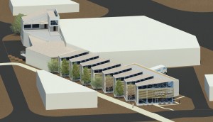 B1. Aerial View: Shows the additions as they attach to the existing structure. View is from the south and east.
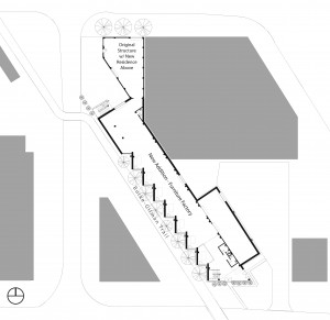 B2. Floor Plan Level One: Includes existing building, addition and storage area. 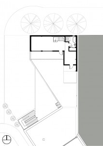 B3. Level 2 - Residence: Atop the roof of the original structure, the living quarters are access via a stairway next to the loading dock.
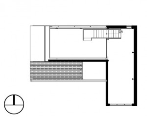 B4. Level 3 - Residence: Upper level of the living quarters. |
Sections & Renderings
- C1-C2 Sections NS and a NW-SE: A section cut north-south through the addition, and looking southeast, shows the buildings primary structural arrangement of post and beam. Following the precedent of the existing building, the addition was designed with CMU walls and concrete columns supporting steel beams.
- C3. Interior Perspective: Looking toward the south-southeast, this perspective reveals the artisan bays established by continuing the sawtooth roof around to the side of the building. In the distance the building entrance, administrative and gallery spaces may be seen.
- C4. Interior Perspective: Looking to the north-northwest, this perspective shows these same work bays as seen from the gallery space above the main floor.
- C3-C4. In both perspectives, the northern party wall may be seen, opposite of the work bays. The party wall runs along the neighboring building, and provides the edge from which the resides.
|
* |
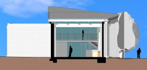 C1. Sections NS and a NW-SE: Section of the factory addition, just north of storage area. Shows the post and beam structural elements and the second story gallery area further down. Drawn in Revit Architecture.
 C2. Longitudinal Section: Cut along the NW-SE axis of the factory addition, shows the truss systems, work bays and factories second floor gallery space. 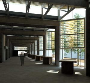 C3. Interior Perspective: Factory floor, looking toward the south-southeast. Shows the individual artisan bays, shading devices and the second gallery level in the distance. Drawn and rendered in Revit Architecture. 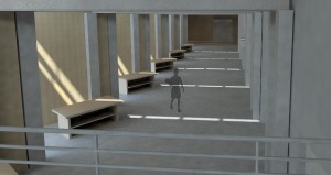 C4. Interior Perspective: Looking north-northwest, shows the individual artisan bays and connection to the original building in the distance. Drawn and rendered in Revit Architecture.
|
Tectonic Model
- D1. Axonometric Outline for Tectonic Model: Plans for the factory addition and owner residence were then translated into a building section (and elevation – not shown) from which laser cutting files were developed.
- D2. Tectonic Model: Utilizing homasote and plywood for a base, the model was constructed primarily of pulp board, okoume, bass wood and foam core board, an clearly demonstrated the tectonic basis for the design.
- D3. Tectonic Model – Detail: A detailed view of the models roof support showing it to consist of welded metal trusses atop steel beams, themselves supported by concrete columns. The metal trusses are basswood finished in iron paint.
|
* |
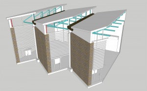 D1. Axonometric Outline for Tectonic Model: Shows intended model to be developed to demonstrate key structural aspects: column and beam, CMU wall, roof trusses and artisan work areas. Drawn in Revit, exported to Sketchup and modified in Photoshop. 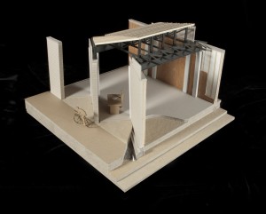 D2. Tectonic Model: A general view of the model shows the artisan bay concept, location of Burke-Gilman Trail, and the structural make up of the design. 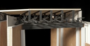 D3. Tectonic Model - Detail: Shows tectonic model detail; outlining the roof trusses made from welded steel angles.
|
Context Model
- E1. Context Model – General: The context model was designed as part of the final review. This model was was constructed of e-flute cardboard, and was cute and scored primarily on the laser cutter. Shown without the supporting context model, the long linear aspect of the addition becomes apparent.
- E2-E3 Located in Site Model: Located in Site Model: Once placed in larger context model, the fitted nature of this design may be seen, with the addition closing hugging the Burke-Gilman Trail. From the southern vantage point, one sees the connection of the addition to the existing building, and from southeast vantage point the customer entrance is seen.
- E4-E5. Detail of Context Model: Detailed images provide two views of the residential addition atop the original structure. With CMU walls, the language of the original structure is provided, and access is enabled by a stairway to the south of the loading dock (not shown). The northern view shows the residence clerestory windows and skylight on the upper level.
|
* |
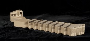 Context Model: Shown without the supporting neighborhood model, from a southern view, this image demonstrates the linear nature of the designed furniture factory. 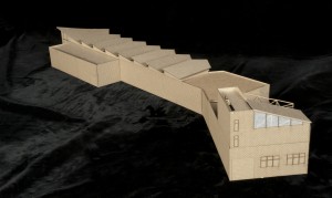 E1. Context Model - General: Shown without the supporting neighborhood model, from a northern view, this image demonstrates the modular nature of the design where it joins the party wall. 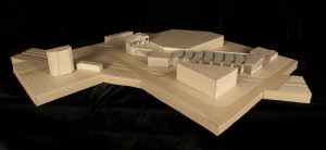 E2. Located in Site Model: Placed into the site model, the context model reveals the relationship with the surrounding neighborhood. View is from the south. 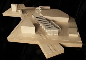 E3. Located in Site Model: Set into the larger neighborhood context model, from a southeastern vantage point. 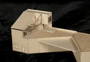 E4. Detail of Context Model: Shows the south-southwestern side of the residential addition and the existing building below; access to roof via stairs to the right of factory entrance (not shown). 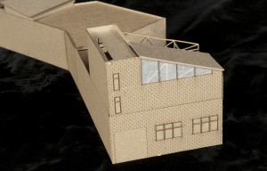 E5. Detail of Context Model: Shows the northern side of the residential addition to the existing building below, including clerestory and skylights. |


