ARCH503 – Architectural Design Studio III – led by Joel Loveland
Summary
Taken autumn quarter 2010, Architectural Design Studio III was created to provide exposure to the concepts surrounding integrated design within the context of a high-rise urbanized environment – striving to meet the goals of the 2030 Challenge – and within the framework of a commonly known architectural model: the public school.
This studio strove to take a small parcel of land in urban Seattle, and transform it into the first high-rise elementary school. Neighbored on the west side by a ten story retirement center, the site was contained on the north end of a block in Seattle’s South Lake Union neighborhood, and faced the challenges of providing adequate light, ventilation and water, while at the same time meeting regulatory requirements for schools, and making the entire facility highly energy efficient.
Program
The program called for a school for 550 children in six elementary grades, and consisted of a traditional mix of classrooms, joint study rooms, specialized
classrooms such as art and music, a library, gymnasium, cafeteria, administration
and services, parking and bus drop off equaling a conditioned interior space of
about 90,000 sq. ft. on approximately 22,000 sq. ft. of site.
The design of the school was to tell the story of its immediate landscape,
and speak conceptually and materially to the nature of urban living on this site and
more broadly in the Pacific Northwest. Materially, the facility needed to utilize
passively sources for illumination, heating and cooling as their primary source of
environmental control and domestic hot water. The school was to be designed so
as to minimize water use and waste treatment and undertake ecologically appropriate use of materials and methods of construction.
Concept & Approach
- A1. Location Overview: Since the program called for the building to be 2030 Challenge compliant, targeted reductions in energy use were planned for by employing a variety of efficient/sustainable systems, including daylighting, passive ventilation, water collection, photovoltaic cells, and added mass and insulation in exterior walls/roof.
- A1. Location Overview: The starting point for me was the site itself. The 22,000 sq ft site was located at the north end of a undeveloped block, zoned to a height of 160′. Across the street, to the west, was a 10 story retirement complex. The challenge in this circumstance would be to design a 8-10 story elementary school on the north side of another highrise, and implement full daylighting through the building.
- A2. Concept: The resulting design created a elementary school which was designed from the inside out; starting with the very base concepts of full daylighting and narrow floor plates. Thus, and inverted L was formed; placing the building core in the northwest corner of the site, and opened the wings to the east and south, forming a self supporting double channel.
- A3. General Building Configuration: The next challenge was to encorporate a large gymnasium into the building, and also have it day lit – while also providing substantial underground parking for the building. To accomplish this, the gymnasium was placed one story above the street – creating in effect a raised solar plinth, allowing the gym, classrooms and support areas to utilize daylighting. Raising the gym in this manner also created space beneath it (at street level) to create a garage entrance and primary school lobby/drop off point. The existing structure to the west also benefited the project by providing shadowing from direct afternoon sunlight.
- A4. Stacked Program Diagram: The building was vertically laid out with the buildings primary entrance on the north side, at street level. Generally, the first three levels contain the support areas (administration, loading dock/storage) and common use areas (two levels of dining/commons area, gym, library and computer lab), in addition to four levels of below grade parking.
- A4. Stacked Program Diagram: At the fourth level, the classroom teaching areas began with the kindergarten areas. Levels five to nine house the regular classrooms and common learning areas for grades one through five. Above level nine are the specialty teaching areas for music and art.
- A4. Stacked Program Diagram: To facilitate multi-grade (mixed age) learning, local stairs were placed at the inside corner on the south side (K+1, 2+3, and 4+5). Primary vertical circulation was otherwise achieved by the main stairway (or elevators when necessary).
|
* |
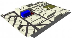 A1. Location Overview: Created for initial site analysis. This Sketchup model shows the site (red) and potential future development to the south (blue) on September 21st, 1 pm. 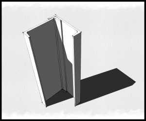 A2. Concept: Two steel channels joined into an angle, opened to the sun. Simple drawing demonstrates the solar access planned for the classrooms as a requirement of design. 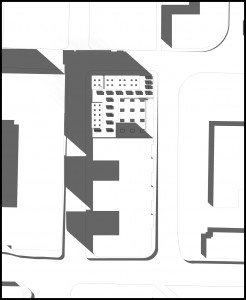 A3. General Building Configuration: Shows the local context and final layout of the building. Shaped into an L, the building opens to the sun, and places the gym one story about the street - creating an solar plinth where daylighting nearly all spaces becomes possible. 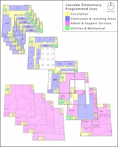 A4. Stacked Program Diagram: Shows the planned layout of program, with four levels of parking |
Integrated Design
- B1. Ecotect RAD Luminance Analysis: Once the basic layout was established, the building was checked for daylighting viability. Since the building floor plates were intentionally kept to a maximum of 50′, the design was assured of creating enough classroom daylight for tasks, and sufficient daylight everywhere else for tasks. An Ecotect analysis was undertaken to confirm this, floor-to-floor.
- B2. Ventilation and Lighting Diagram: In order that the classrooms/teaching areas might have balanced daylighting within them, the design scheme utilized perimeter windows and glazed relights between the classroom the adjacent corridor.
- B3. Daylighting Models: By modeling expected daylight all levels, the added provision of glazed relights, while not adding large amounts of usable light, did manage to create a brighter room, and tended to balance the daylight coming from the perimeter glazing.
- B4. Ventilation Diagram: The building also utilized separated heating, cooling and ventilation systems rather than a single HVAC system.
- B4. Ventilation Diagram: The system was configured to operate during the cooler months with perimeter hydronic heating provided by single units on every third floor. While cooling was not called for (as the building is anticipated to be closed during the summer), chilled beam technology would have been employed if necessary.
- B5. Typical Ventilation Plan: Active ventilation was maintained during cooler months with small venting systems every three floors which drew in fresh air, passed through a highly efficient (85%) heat recovery system, and was then distributed, being reheated (hydronic) if necessary.
- B5. Typical Ventilation Plan and B2. Ventilation and Lighting Diagram
 assive ventilation is made possible during fall and spring periods with operable windows in the classrooms; pass through vents in the interior partitions, exhaust ducting (shown in black) connected to dedicated thermally induced exhaust stacks located on the southeast corner of both wings. assive ventilation is made possible during fall and spring periods with operable windows in the classrooms; pass through vents in the interior partitions, exhaust ducting (shown in black) connected to dedicated thermally induced exhaust stacks located on the southeast corner of both wings.
- B6. Water Management Diagram: The building harvests rainwater (during wetter months), and gray water from the buildings operation. The water is filtered and then held in 1100 gallon cisterns on four floors, and was used to flush toilets. Excess rain water is routed to the green roof atop the gym where it may evaporate naturally.
|
* |
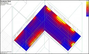 B1. Ecotect RAD Luminance Analysis: Shows sufficient day light capabilities by placing classrooms on the north and west sides of the wings and the circulation on the south and east sides.  B2. Ventilation and Lighting Diagram: Shows the planned access for solar daylighting and planned passive ventilation. Shows both seasons to two separate floors. 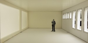 B3. Daylighting Model - North Wing: Shows typical classroom in west wing, and sufficient daylight for classroom task; measured on levels five through nine. 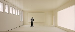 B3. Daylighting Model - West Wing: Shows typical classroom in west wing, and sufficient daylight for classroom task; measured on levels five through nine. 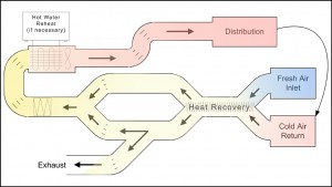 B4. Ventilation Diagram: Ventilation Diagram: Shows active ventilation system and heat recovery unit. Primary heating supplied by hydronic wall units (not shown). 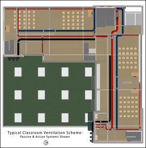 B5. Typical Ventilation Plan: Shows routing of active ventilation system on typical classroom floors. Red is supply (pre-heated from recovery), blue is return and black is passive exhaust. 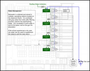 B6. Water Management Diagram: Shows the collection and retention of rainwater and gray water for toilet flushing or evaporation on green roof located atop gymnasium. |
Interior Perspectives
- C1. Classroom Perspective: An interior perspective of a typical classroom shows the utilization of daylight for tasks. In addition to daylighting, the lighting controls in the room permit split sensors, which can turn off perimeter lights when the amount of daylight is sufficient.
- C2. Commons Perspective from Stairs: An interior perspective from the main stairwell, between floors one and two, looking southward, shows the lower commons and local stair to the upper level. Both the lower and upper commons utilize daylighting from a combination of windows on the western wall and the skylights in the gym.
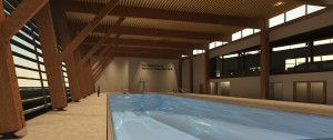
- C3. Gymnasium Perspective: An interior perspective of the gym (taken from the southeast corner, looking to the northwest) reveals the daylighting possible from the skylights atop the roof, and vertical glazing located on the east upper wall wall of the gym, facing eastward.
- C3. Gymnasium Perspective: The lighting from within the gym also supplements perimeter daylighting in the library (level three), the computer lab and kindergarten (level 4).
|
* |
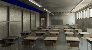 C1. Classroom Perspective: Typical classroom; this one on the north wing, fifth level (first grade), looking west. 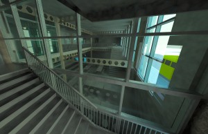 C2. Commons Perspective from Stairs: From main stairs between levels one and two, looking south into the Commons area.
 Holding Image |
External Perspectives
- D1. Aerial Perspective: Viewed from the north, looking to the southeast at the front of the building. Entry may be seen as well as ventilation air intakes on the west wall.
- D2. Street Level Perspective: Looks to the southwest shows the east side of the building. The vertical glazing of the gym is visible as is the south thermal stack and garage entrance.
|
* |
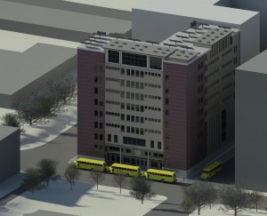 D1. Aerial Perspective: Viewed from the north-northwest. Shows the student loading zone and placement of classroom glazing on the north and west walls. 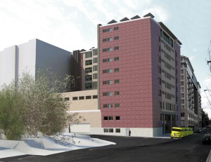 D2. Street Level Perspective: Looking west, south-west at the northeast corner of the building. |
Axonometric View:
- E1. Split Axonometric View: Reveals the interior of the building in detail; split along the west wing. The view is from the north to the south.
- E1. Split Axonometric View: Image shows the building in its entirety, from the four levels of parking to the photovoltaic cells on the roof.
- E1. Split Axonometric View: Note the connecting stairs between grade levels and the gym visible through the vertical glazing on levels two through four.
|
* |
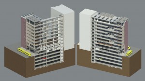 E1. Split Axonometric View: Sectioned on the north-south axis in the west wing of the building, this axo shows the overall mass of the building as well as its structural program. |


