ARCH504 – Furniture Studio – led by Kimo Griggs
Summary
Taken winter quarter 2011, the Furniture Studio is centered about the design and creation of an individual piece of furniture, such as a table, chair, desk or other item through to completion. The approach is based on the “studio furniture” movement in the U.S. where individuals design and build individual pieces of furniture in small-scale shops (rather than mass-producing furniture). The focus of the quarter is the use and mastery of fabrication techniques using wood, metal or other materials, sufficiently enough to complete the project within the 10 week time frame.
Program
My chosen project was the creation of a lounge chair, sized to my body, and constructed solely of components fabricated within the confines of the wood or metal shop.
Design & Layout
- A1. Prototype Chair: The initial design of the chair was based up a desire to develop a piece to assist in relaxing me. To accomplish this, a curved seating arrangement was established which, when reclined would raise the legs to the height of the heart. Built of inexpensive plywood and planks, constant adjustments were made to establish this starting shape, around which the remainder of the chair would be developed.
- A2. Refined Curve: Following the completion of the prototype, the chairs “curve line” was scanned into the Rhinoceros CAD program for additional development. There, the configuration and design of supporting hardware elements would be created.
- A3. Final Design: After the primary shape was determined and loaded into Rhino, the structural elements of the chair were developed. Then the connecting and reclining hardware which would be built later one were designed and added to the CAD version of the chair. In order to realize this design, much of the work would have to be done on the computer numerically controlled (CNC) machine – both in the forming and finishing stages.
|
* |
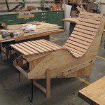 A1. Prototype Chair: Working in inexpensive woods to develop the most comfortable seat possible.
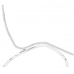 A2. Refined Curve: After the prototype, development in Rhino to resolve other issues with the design. 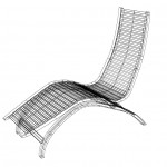 A3. Final Design: After resolving issues of balance, structure and support, questions of hardware and the reclining mechanism were approached. |
Mold Making & Wood Selection
- B1. Mold Cutting: Following the CAD development of the chair, primary rail and leg molds were cut from MDF on the CNC machine. Eight layers of 3/4″ MDF were joined together to make molds of sufficient strength.
- B2. Completed Rail Mold: Once the MDF cutouts were finished, assembled and sanded smooth, final finishing was undertaken to ensure that imperfections on the face of the mold were not present to translate to the final piece. To accomplish this, fiberglass resin was added and sanded smooth until the mold would produce a perfectly shaped rail.
- B3. Raw Veneer: Ash was chosen for the primary material in this project because of its flexibility, availability and fairly low cost. Two large flinches of ash veneer were purchased from Eden Saw of Tacoma, WA and delivered to the shop at Gould Hall.
- B4. Pack Creation: From each finch, packs were created which would yield the most solid, most attractive grain pattern. Since the rails ungulate in two directions, the pattern sought was one wherein the viewer could follow the grain path from the top from the top of the chair to the bottom.
|
* |
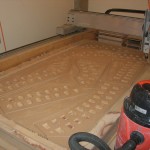 B1. Mold Making: Cutting the molds from MDF on the CNC machine. 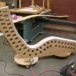 B2. Completed Rail Mold: The primary rail mold sits ready for a test molding of scrap. 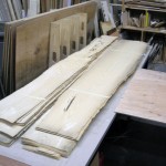 B3. Raw Veneer: Purchased flinches of ash veneer soon after arrival at Gould Hall. 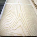 B4. Selecting Packs: Each flinch was marked and trimmed down, depending upon the pattern of the grain. |
Molding Rails & Legs
- C0. Gluing Up: After packs of veneer were selected and cut to a rough size, epoxy was rolled onto each side of each veneer while a countdown timer ran.
- C1. Test Mold: Before the actual rail molding was conducted, a test mold was undertaken first. This test mold would result in a modeling rail which would be used to test assumptions and conditions surrounding the actual rail molds. The test mold also allowed us to develop a sequence of construction, movement and clamp placement to avoid errors in the final piece.
- C2. Rail #1: Once the pattern and method for gluing up was established, a time-sequenced plan was laid out for the glue-up. In these sessions, furniture maker and instructor Steven Withycombe guided me in placing and properly clamping the package to ensure a successful outcome. A gifted furniture maker, Steve’s support and guidance were invaluable in the design and execution of the chair.
- C3. End Clamping: After placing the glued up package into the mold, clamping pressure is exerted from the center of the rail (the area of the sea) outward toward the head and foot. This is done to ensure a consistent pressure level and to avoid slippage between the layers of glued veneer.
- C4. Rail #2 – Time to Cure: After glue-up, placement and clamping, the entire package is allowed to cure for approximately 24 hours before the rough mold of the rail is removed for further finishing.
- C5. Legs Form: The legs of the chair were formed in a similar manner, although while each of the main chair rails had to be formed individually, the chair legs were formed from a single mold which was then cut into two separate pieces. Following the molding process, all pieces came out rough, and had to be cut down, squared and cleaned up. This release of the leg mold shows the rough condition following the initial process.
- C6. Rough Blank: Once the molded piece has been released, cut down and cleaned up, it was sanded and shaped into its final form. Only then could the rail be taken to the CNC for the next stage of the process.
- C7 Finished Blank: After much rasping, chiseling, sanding and squaring, the finished blank is ready for the CNC processing.
|
* |
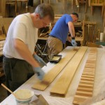 C0. Glue Up: With the countdown timer running, author (foreground) and instructor roll epoxy onto each face of veneer within the pack. 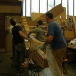 C1. Test Mold: Placing "the package" after gluing it up. 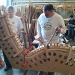 C2. Rail #1: Author sets clamps with instructor Steven Withycombe. 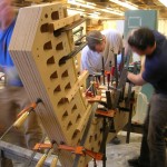 C3. End Clamping: Once the middle is set, clamps outward toward the ends are also set. 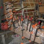 C4. Rail #2 - Time to Cure: After all the clamps are set, the entire set is allowed to cure for about 24 hours. 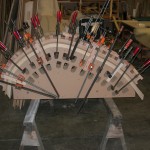 C5. Legs Form: At a later time the lamination for the legs were created in a similar manner. 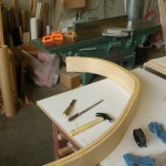 C6. Rough Blank: Once the epoxy had cured, the legs and rails were released from the mold in preparation for cutting and finishing. 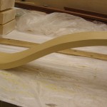 C7. Finished Blank: Finished blank of one of the two rails, each had to be squared and finished before any CNC work could be done.
|
CNC Cutting of Rails
- D1. Rails Base: The CNC was used to create the shape of the rail as well as to mortice the slats in the seat. To secure the rail blank for cutting the shape of the rail was cut into a sheet of 3/4″ plywood which was itself screwed to the bed of the CNC.
- D2. Screwing It Down: Once the plywood base was secured, the rail blanks were inserted and secured with wood blocking. Throughout the CNC process I was assisted by Jeff Hudak who was also serving as an instructor in the studio.
- D3. CNC First Pass: The first steps of the CNC process carved the edge of the rail blank to 1/2 of it’s final shape. This was accomplished with a cutting file derived from the Rhino CAD file, and enabled the rail to be shaped on two different axises.
- D4. CNC Final Pass: In the final passes, the CNC cut mortice pockets in the rails to accept the solid ash slats.
- D5. Finished Rails: Once the rails were finished, they would be dry fitted with the slats to ensure fit, and only then have the outside edges cut off (on the band saw) prior to final assembly. At this time, 54 slats of individual length were cut with 3/8″ ears (for the corresponding mortice).
- D.6 Hardware Creation: All of the hardware on the chair was built with 1/8″ plate steel and 1/4″ steel rod. The plate steel was cut on the plasma cutter from plans originating from the Rhino CAD file. From these base pieces, hinges were welded, brackets bent to shape, etc.
|
* |
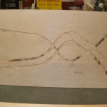 D1. Rails Base: Base to hold the rail blanks in place during the CNC process was itself CNC'ed from 3/4" plywood. 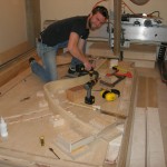 D2. Screwing It Down: Jeff Hudak provides guidance in the securing of the rail blanks to the CNC bed. 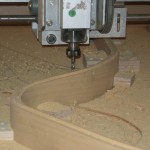 D3. First Pass Rail #1: CNC makes an initial pass to cut the rail blank down to roughly twice its finished size. 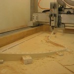 D4. CNC Fifth Pass Rail #2: After cutting the intial shape the CNC then came back to cut mortice pockets.
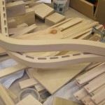 D5. Finished Rails: Both rails #1 and #2 are shown in position relative to each other.
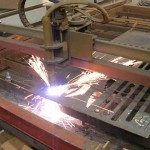 D.6 Hardware Creation: Hardware for the chair was created from 1/8th plate steel; cut on the plasma cutter. |
Fitting & Finishing
- E1. Dry Fitting of Chair: Following the completion of cutting the inside edge of the rails, the chair was dry fitted together to check for fit with the slats in the mortice pockets. The slats had been cut earlier from a solid 8′ beam of ash.
- E1. Dry Fitting of Chair: At this stage, only the inside edges of the rails had been cut down to their final size. The outside edges where still in rough, and were left that way until just before the final glue up, when they were removed with a band saw. During final glue-up, the “corner ears” which had been removed were taped back into place to provide positive clamping surfaces
- E2. Dry Fitting of Legs: The legs were also dry fitted, and fitted out with wood biscuits. In this case, special attention was paid to the connections to ensure that the base of the chair would not rack once it was assembled and was placed under the load of a user.
- E3. Chair Finishing: The chair was finished with 16 coats of simple shellac. Shellac was chosen over other finished because of it’s ease of removal and refinishing. It was also chosen to all many coats to be applied within the shorter time frame (24 hours) before final review.
- E4. Blackening Hardware: The steel hardware was cut, welded and fitted out for screws. It was then blackened using a black metal oxide solution and Penetrol conditioner.
- E5. Finished Chair: The finished chair was one which was light to move, comfortable to sit it, and very relaxing (when sitting or reclined).
- E6. Finished Chair Upright: The chair in this position allows the user to read or do other tasks which require being upright.
- E7. Finished Chair Reclined: When reclined, the chair elevates the user’s lower extremeities to be elevated to the level of the heart or slightly higher. The heart works less as a result, and one relaxes considerably.
- E8. Finished Chair Detail: Blackened steel axle and hinges, joined by bronze bushings are shown beneath the the chair; following the primary cross plate which is usually hidden beneath the seat (when upright).
|
* |
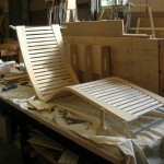 E1. Dry Fitting of Chair: 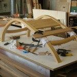 E2. Dry Fitting Legs 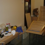 E3. Chair Finishing: 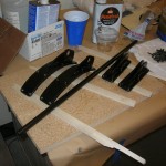 E4. Blackening Hardware: 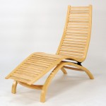 E5. Finished Chair: 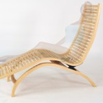 E6. Finished Chair Upright: 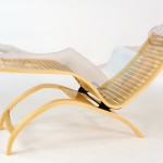 E7. Finished Chair Reclined: 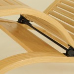 E8. Finished Chair Detail: |


